
Equipment
- Slurry and dredge pumps
- High-pressure valves and chokes
- Mechanical seals and rotating equipment
- Hydrocyclones and abrasive-fluid systems

SLURRY, HIGH-PRESSURE & ABRASIVE FLUID SERVICE
Control erosion, wear and leakage by matching carbide composition, surface finish and fit to the fluid, solids, pressure and speed.
APPLICATION FIT
WORKING CONDITIONS
A useful recommendation starts with the load, environment and mating system. Include measured data when available and describe field conditions when it is not.
COMMON FAILURE MODES
COMPLETE TOOL + CARBIDE
Capability note: complete assemblies are evaluated against the drawing, sample, production volume and available technical evidence. No field-life claim is made until a controlled trial is completed.
VERIFIED COMMERCIAL EVIDENCE
These published product photographs and specifications support material, blank and custom-geometry discussions. They do not show a finished customer valve, pump or seal assembly.
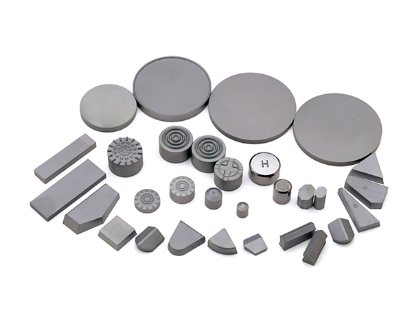
Ruixin studio product photograph. Use it as evidence of current custom-shape capability, not as a claimed pump or valve installation.
Open source product →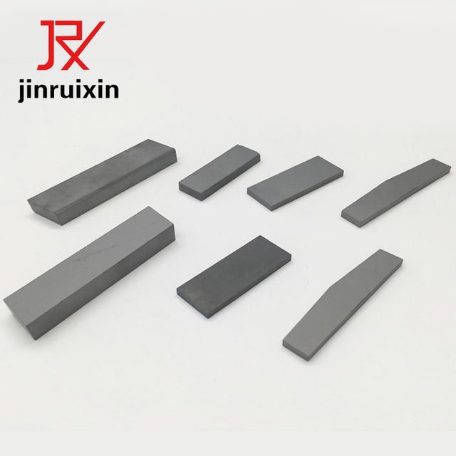
Ruixin studio product photograph of carbide strips. Relevant to wear strips and liner concepts; final attachment and geometry remain drawing-specific.
Open source product →Published strip range: width 2–60 mm, thickness 1–20 mm and length up to 330 mm standard, with custom lengths on request.
View dimensions →Published supply conditions are sintered or ground and lapped; standard strip flatness is listed as ±0.05 mm. Seats, rings and fitted parts remain drawing-specific.
View tolerance scope →WC-Co, WC-Ni and WC-NiCr options are published for application review, with grain and binder selection tied to corrosion, erosion and mechanical load.
View material options →Published strip samples are 1–10 pieces and listed at 3–5 business days; bulk strip orders are listed at 2–4 weeks. Custom formulations follow a separate development schedule.
View sample terms →Evidence still required: real valve-seat, seal-ring, sleeve or pump assembly photographs; a redacted MTR/dimensional report; and an anonymous service case tied to media, pressure, speed and observed failure. Precision tolerances are not claimed without the approved drawing.
Submit approved evidence or project detailsRECOMMENDED PRODUCT FAMILIES
These families are starting points. Final grade, size, tolerance and assembly scope are confirmed from working conditions.
CUSTOM DEVELOPMENT
Drawing or sample review
Working-condition and failure analysis
Grade, geometry and joining proposal
Sample manufacture and inspection
Field test, feedback and batch release
Carbide system, grain size and binder are selected against the application requirement.
Critical dimensions, interfaces and inspection scope are confirmed before sampling.
Trial quantities and field feedback establish evidence before scale-up.
Inspection and material documents are agreed according to project scope.
CORE TECHNICAL GUIDES
TECHNICAL LIBRARY
Use these supporting articles for selection, failure diagnosis, operating review and purchasing preparation.
FAQ
Share the media, solids content, pressure, temperature, shaft speed, mating material, lubrication, surface finish, dimensions and the observed leakage or wear pattern.
Precision-finished components can be evaluated. The drawing should define critical dimensions, geometric tolerances, surface finish, edge condition and inspection method.
The binder system and carbide microstructure are reviewed against the fluid chemistry and mechanical load. Corrosion resistance should not be selected independently from toughness and wear requirements.
ENGINEERING SUPPORT
Share the equipment, material, current part and wear pattern so the recommendation starts with the real working condition.
ENGINEERING INQUIRY
Leave your contact details and a short requirement. Engineering will follow up for drawings and working conditions when needed.
 English
  Russian
  Spanish
  French