
Gauge-row concentration
Localized gauge wear can point to abrasive wall contact or hole-control conditions. Compare it with face-button wear before deciding what to change.

ROCK DRILLING / FAILURE-LED SELECTION
Button wear, fracture location, retention and hole behavior help determine whether the next trial should change grade, profile, fit or drilling parameters.
Rock hardness alone is not enough. Abrasivity, fracture pattern, water, impact energy and bit design also matter.
ENGINEERING LOGIC
Localized gauge wear can point to abrasive wall contact or hole-control conditions. Compare it with face-button wear before deciding what to change.
DTH drilling combines impact and abrasion. A more abrasion-biased candidate may increase chipping risk if impact toughness, button support or operating parameters are not suitable.
Thermal checking, inadequate flushing and matrix washout should be separated from simple carbide wear before a grade change is proposed.
PRE-TRIAL CHECKS
| Check | What to inspect | Why it matters | What to send |
|---|---|---|---|
| Fit & retention | Mating dimensions, interference and button-seat condition | Separates material failure from fit or retention failure | Drawing + close-up |
| Bit body | Washout and support around the insert base | Weak support can accelerate damage around the button | Side-view photo |
| Flushing | Cuttings removal, blocked passages and cooling | Regrinding and heat can change the observed wear pattern | Pressure + passage data |
| Operating parameters | Impact pressure, rotation and feed | Parameter imbalance can concentrate wear or fracture | Rig settings |
| Wear distribution | Gauge-row versus face-button wear | Distinguishes localized wear from a more general pattern | Two comparison photos |
| Formation | UCS, mineralogy, abrasivity, fractures and water | Rock hardness alone is not enough for selection | Available formation data |
ROCK-DRILLING FIELD ARCHIVE
These authorized photographs document rock-drilling equipment, new and inspected bit assemblies, a severely damaged tricone bit and a carbide-button product. They provide application and failure-analysis context; they are not presented as a traceable customer performance case or proof of drilling-life improvement.

Equipment context for discussing drilling system, formation, flushing and operating parameters. The photographs do not identify a measured project result.

Unused bit reference for reviewing cone layout, insert distribution, gauge protection and threaded connection.

Inspection context showing why full-bit, cone, seat and adjacent-insert observations should accompany close-up wear photographs.

Severe damage and insert loss require checks of cone, bearing, seat, support and operating load before any carbide-grade change.

Product reference for button profile and layout discussion. Fit, interference and inspection remain specific to the approved bit design.
GRADE SPECIFICATION REFERENCE
| Property | 2020 specification reference |
|---|---|
| Grade | SS20CB |
| Chemical composition | WC 90 wt%; Co 10 wt% |
| Density | 14.50 g/cm³ |
| Rockwell hardness | HRA 86–86.5 |
| Vickers hardness | HV30 1000–1050 |
| Transverse rupture strength | TRS ≥2600 MPa |
| Average grain size | 5–6 μm |
| η phase | None |
2020 grade specification reference only. Current-order composition, properties, inspection methods and acceptance limits must be reconfirmed before production. These values are not a current batch certificate, drilling-efficiency claim or service-life promise.
PUBLISHED PRODUCT EVIDENCE
| Published grade family | SS12C, SS16C, SS20C, SS16CB–SS20CB, SS15CT and SR11C |
|---|---|
| Published range | HRA 86.5–90; TRS at least 2200–2900 MPa; grain size 2–8.5 μm |
| Published profiles | Spherical, ballistic, conical and chisel |
| Catalogue fit references | Press-fit h5/h6 and ±0.005 mm; final fit requires approved mating dimensions |
| Published trial quantities | Rotary inserts 20–50 pieces per grade; buttons 50–200 pieces |
| Published timing references | Samples typically 5–7 days; bulk 3–5 weeks after review |
| Inspection scope | Hardness, density and grain structure; final dimensions and fit agreed per drawing and order |

Product-family evidence — not a field-result claim.
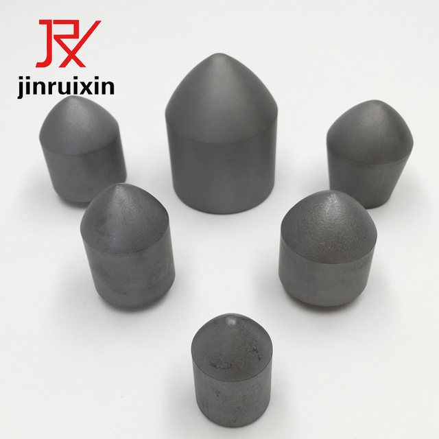
Product-family evidence — not a field-result claim.
CONTROLLED VALIDATION
Gauge-row and face-button views make the starting pattern easier to compare.
Engineering checks the carbide together with the bit body, fit and operating data.
Confirm the relevant product-family trial quantity and inspection scope before sampling.
Compare the trial against the baseline in a controlled formation before batch release.
ENGINEERING HANDOFF
A likely mechanism to verify, based on wear photos and operating data.
A candidate grade / profile direction and the conditions that still need confirmation.
The mating dimensions, retention and support details to confirm before sampling.
A controlled trial quantity, inspection scope and field-recording checklist.
QUICK FACTORY-PRICE CHECK
PHOTO GUIDE
 English
  Russian
  Spanish
  French